When a mobile manipulator beats a fixed arm — and when it doesn't
A realistic framework for the integration and positioning trap that catches first-time buyers
The machine-tending pilot that stalled
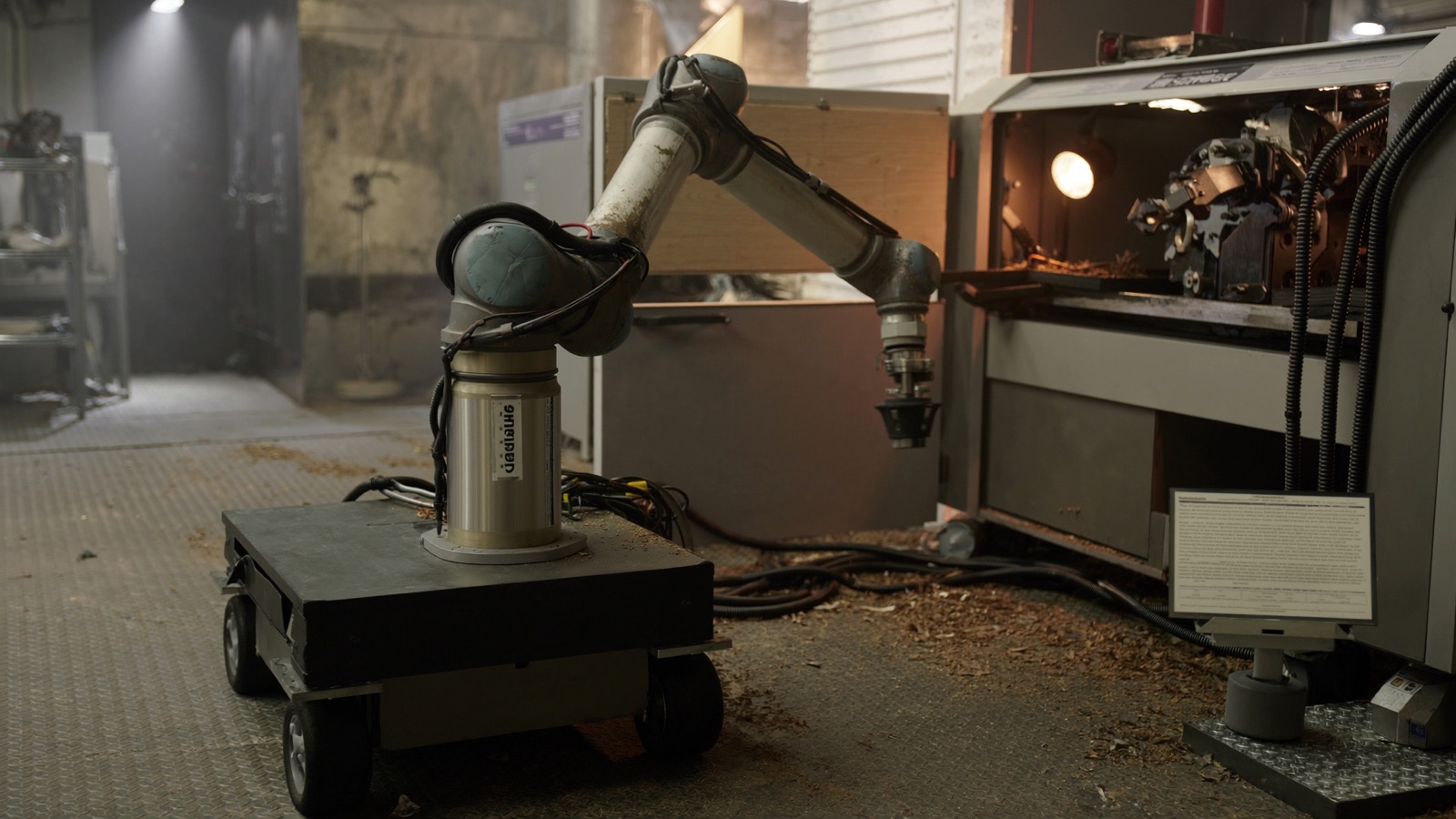
A mid-size contract manufacturer installed a wheeled mobile base paired with a 6-axis collaborative arm — a mobile manipulator — to tend three CNC lathes arranged in an L-shape roughly 40 metres apart. The pitch was compelling: one robot circulating the floor instead of three fixed arms plus an automated material-handling system. The numbers looked clean on paper.
Six months in, the project was running at 40 percent of projected throughput. The root cause was not the arm and not the base taken individually. It was the compound error that accumulates when a mobile platform navigates to a station, stops, and then the arm tries to pick a part from a fixture.
The base, even with a premium navigation stack, reproducibly parks within ±10–15 mm of target. The arm's mechanical repeatability was ±0.05 mm — well within the tolerance for the lathe-load task. But the arm's effective repeatability at the end-effector, relative to the fixed fixture, was the base positioning error plus the arm's own error. That combined number — sometimes called positioning repeatability after navigation — ran to ±12 mm on a bad park. The gripper jammed parts, triggered safety stops, and required a human recovery every two to three hours.
This is the positioning trap. It catches buyers who read the arm's spec sheet carefully and read the base's navigation spec carelessly, or who treat the two as independent systems.
What "repeatability" means across three layers
Before building a decision framework, buyers need to disaggregate three distinct repeatability concepts that vendors — and even integrators — often conflate:
Arm mechanical repeatability is the most-published number: how precisely the arm's TCP (tool centre point) returns to the same pose given the same joint angles. For a contemporary collaborative arm (cobot), this is typically ±0.025–0.1 mm. This is the number on the cobot's datasheet. It says nothing about where the cobot is sitting in the room.
Base navigation accuracy is how closely the mobile base parks at a programmed goal pose (x, y, heading). With lidar-based SLAM (simultaneous localisation and mapping), this is commonly ±5–15 mm laterally and ±0.5–1° in heading. Some platforms add visual fiducials or docking pins to tighten this; without them, the floor-level number dominates everything above it.
End-effector positioning repeatability after navigation is the compound number that actually matters for manipulation tasks. It is roughly the root-sum-square of the base positioning error and the arm's own error — but because the arm amplifies angular errors at the base, the relationship is not simply additive. A 1° heading error at the base, combined with a 600 mm arm reach, produces approximately ±10 mm of TCP displacement in the worst direction.
The practical implication: for any task with part tolerances tighter than ±5 mm, a mobile manipulator without active re-localisation at the workstation will fail more often than it succeeds.
Three compensating architectures
The industry has converged on three approaches to close the gap between base navigation accuracy and arm task tolerance:
Fiducial-anchored re-localisation. A camera or structured-light sensor on the arm detects a fixed marker (AprilTag, ArUco, or precision-machined dowel pin) at each station. The arm's controller computes a correction transform and adjusts the pick/place programme accordingly. This adds latency — typically 2–5 seconds per station visit — but achieves effective end-effector accuracy of ±0.5–2 mm relative to the fixture, regardless of how the base parked. Robotnik's RB-KAIROS+ platform, which pairs an Omnibase with a UR or similar cobot arm, uses this pattern in standard deployments.
Precision docking. A physical dock at each station mechanically constrains the base position to ±1–3 mm. The base drives to approximate position, then the dock (cone-and-socket or rail) pulls it into repeatable alignment. No perception correction is needed at the arm level. The tradeoff: docks must be installed at every station, limiting the "go-anywhere" flexibility that motivated the mobile manipulator purchase in the first place.
Force/compliant insertion with generous approach clearances. For tasks that tolerate compliance — inserting a part into a loose fixture, pressing a button, opening a cabinet — the arm's force-torque sensor can accommodate the navigation error without re-localisation. This is the lowest-cost path but only works when the task physics allow it.
Most successful production deployments use a combination: fiducial re-localisation for tight picks, force compliance for loose inserts, precision docking for the highest-value stations.
When the combined platform genuinely wins
With those mechanics in mind, a mobile manipulator beats a fixed-arm-plus-AMR architecture in a specific cluster of conditions:
| Condition | Why it favours mobile manipulation |
|---|---|
| 3+ stations, each lightly utilised | A single robot circulating 4–6 stations can achieve higher composite utilisation than one arm per station sitting idle between parts. Utilisation is the core economic argument. |
| Station layout changes frequently | Reprogramming navigation waypoints + fiducial positions is faster than rewiring conveyors or relocating fixed-arm pedestals. |
| No floor space for fixed-arm footprints | Mobile bases occupy station footprint only when present; fixed arms occupy it permanently. In dense cells, the floor reclamation matters. |
| Task variety exceeds what a single fixed arm can reach | A mobile manipulator can reach into a machine enclosure, then traverse to a wash station, then load a packaging cell — tasks spread across a floor area no fixed arm spans. |
| Light payload, moderate precision (>±0.5 mm) | The sweet spot for most cobots on mobile bases is payloads below 10–16 kg and tolerances that fiducial re-localisation can achieve. |
A mobile manipulator loses — often badly — when any of the following apply:
- Cycle times are tight. Navigation transit plus docking plus re-localisation adds 15–60 seconds per station visit. A fixed arm cycles in 3–8 seconds. If station utilisation is already high, the mobile robot cannot keep pace.
- Part tolerances are tighter than ±0.3 mm. Even with fiducials, achieving sub-0.3 mm repeatability after navigation requires exceptional docking fixtures and careful thermal management. For precision machining tolerances, a fixed arm on a rigid pedestal is almost always more reliable and cheaper.
- Payload exceeds the cobot's rated capacity at extended reach. Most cobots on mobile bases are rated 10–16 kg at the flange — but that rating degrades at full reach. A 12 kg part at 900 mm reach may be at or past the arm's rated moment, causing speed reductions or faults that eliminate any throughput benefit.
- The environment is unstructured or has unpredictable obstacles. Mobile bases require reasonably clean, uncluttered floor paths. A floor that operators use for staging pallets, with variable obstacle patterns, forces frequent replanning or manual interventions that destroy the utilisation argument.
The utilisation leverage point
The strongest single variable in the mobile manipulator business case is utilisation across stations — what fraction of the robot's time is the arm actually performing value-added work (picking, placing, machining-tending) versus navigating, waiting, docking, or re-localising.
A rough benchmark: if the combined transit + docking + re-localisation time per station visit exceeds 25 percent of the task cycle time at that station, the mobile manipulator's effective throughput will underperform a dedicated fixed arm even at a fraction of the fixed arm's utilisation.
For a machine-tending task with a 90-second cycle:
- Navigation + dock + re-localise: 20 seconds = 22% overhead — marginal
- Navigation + dock + re-localise: 40 seconds = 44% overhead — the mobile robot needs to cover 4+ stations to compete economically
This is why the strongest deployment patterns for mobile manipulators involve a hub-and-spoke station layout: multiple machines arranged around a central aisle, each within 30–60 seconds of travel, with a light enough per-station cycle that the robot can realistically complete full circuits.
A three-question pre-purchase screen
Before committing to a mobile manipulation platform, three questions anchor the decision:
What is the part tolerance at each station, and can fiducial re-localisation achieve it reliably? Get vendors to demonstrate positioning repeatability after navigation with your actual fixture geometry — not bench-test numbers on a clean lab floor.
What does utilisation look like at each station, and across the full circuit? Model the cycle: per-station task time, transit time, docking time, re-localisation time, charging overhead. If total productive time falls below 50 percent of shift hours, re-examine the fixed-arm alternative.
How often does the station layout change, and who pays for the reprogramming? If reconfiguration is the primary flexibility argument, validate that your integration partner can execute a station move in hours, not weeks. The flexibility argument evaporates if reprogramming is expensive and slow.
What to read next
For a detailed side-by-side cost model comparing mobile manipulation to fixed arms and conveyor automation, see The real cost of a mobile manipulation cell — the follow-on article in this series breaks down integration engineering, safety, and downtime costs that rarely appear in vendor proposals.
Discussion
0 commentsNo comments yet. Sign in to be the first.